In Eurorack, there are lots of types of modules, with different types of inputs and outputs designed to do different things. The way that the ins and outs of modules are designed can change what they do, of course, but sometimes the differences can be subtle: for instance, why are there separate audio and CV mixers?
What is coupling?
In the context of modular and not, say, trains, coupling is what happens when you patch two modules together. The electrical signal flows out one module, through the patch cable, and into another module’s input. That signal might be alternating current (AC) or direct current (DC). AC signals will come from things like audio oscillators: oscillators make signals that move up and down, generally pretty fast. DC signals will come from places like sequencers, offset generators, or LFOs: unlike audio oscillators, they’re static and they don’t move (or least not very fast). And if an input is DC coupled, you can put a slow or static signal into it; if an output is DC coupled, it’s good for that sort of signal.
A DC-coupled input is pretty simple. Here’s a really basic, not-interesting schematic that illustrates the point. There’s an input going to an op amp and then right out through another jack. The output on this circuit is DC coupled.

A DC-coupled schematic.
Of course, we need the contrasting AC-coupled example, too:
 An AC-coupled schematic. The series capacitor followed by parallel resistor are the key to AC coupling.
If you know a bit about electronics you can probably see what’s happening here in this AC-coupled circuit. If you’re like me and still think a capacitor is probably some kind of hat, let’s explain. You’ll notice that there’s a small difference between these circuits: The AC-coupled version adds the capacitor (labeled C66, the part that looks like this: | | ) in series and a resistor (R24) in parallel with the op amp output.
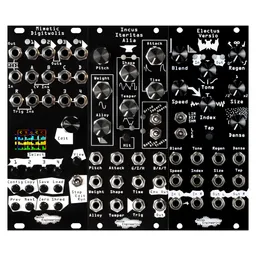
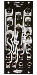
Check out some NE modules:
That’s the symbol for our capacitor. Its placement before the resistor that goes parallel to ground in the circuit is what makes it AC coupled. AC-coupled circuits remove any signal below some frequency threshold. Look back at the figure: what is the frequency of the DC signal? It’s pretty low, or even zero -- as in, it’s not moving. That means that the AC-coupled circuit will filter it out completely.
Does this sound like any familiar utility? Yep, the AC-coupling circuit is a really basic highpass filter. Audio signals are high enough frequency that a super low highpass filter won’t take out anything that we care about. But why would we want to modify a signal at all? Isn’t it good enough on its own? Let’s take a look at some examples of common signals we’ll find in Eurorack.
AC vs DC signals
For our purposes, we’ll consider an AC signal to be any signal in the audio range (roughly 20Hz -20,000Hz, depending on your age and how many concerts you’ve attended). An example of an AC signal would be a sine oscillator at 100hz.
Notice this sine wave has an offset in it and isn’t centered:

An example of an AC signal.
These are relatively high frequency signals.
Contrasting that, a DC signal is anything that doesn’t move at all (or moves incredibly slowly, more on that later). An example of a DC signal would be a step sequence:

An example of a DC signal.
You can see that relative to the AC signal, these signals have a frequency that’s pretty low -- less than one cycle per second (<1 Hz). If we have a DC-coupled input on a module, these very low frequency signals are no problem. For instance, if we run that step sequence into the frequency input of a VCF, it will open and close the filter. BUT if we run it into an AC-coupled input, it acts as a highpass filter and filters it out completely! No signal for you!
AC (audio) signals can also have DC in them, often unintentionally. What? Yes!
When dealing with audio, we don’t want offsets for a number of reasons: it can limit dynamic range, it can damage audio equipment, and it can cause other issues when dealing with audio processing. Let’s look at what AC coupling would do to that initial offset sine wave:

See how it’s centered now? The offset has been removed and it’ll perform much more like we want it to.
How do I know if I want an AC or a DC signal?
Generally, unless you are intentionally using audio-rate modulation for things like FM synthesis, assume your modulation sources are DC signals. Pitch sequences, CV sequences, envelopes and even LFOs will all get filed under DC. AC signals will be anything in our audio path.
Isn’t an LFO an AC signal?
So here’s where it gets weird. An LFO certainly looks like an AC signal, but it’s in the name: they are low frequency. Remember that an AC-coupled circuit is just acting as a highpass filter, so generally, they will filter out LFO signals. If a circuit is AC-coupled to filter out everything below 10hz, a 1hz LFO (which is actually relatively fast for a modulation signal) still won’t make it through. Even though LFOs move back and forth, think of them as DC.
Don’t we sometimes want DC in audio?
Here’s where things get even weirder. Sometimes DC offsets in audio can change how audio processors respond. On occasion we want this, at least in part of our signal chain, as it can create interesting results. A common example is in wavefolders: there will often be an offset control (usually called something else like “symmetry”) that injects a DC offset into the audio signal before it hits the wavefolder to create new sounds. However, if this is the case, the wavefolder will most likely have an AC-coupled output so that the next module in the chain doesn’t have any issues. Basically, both AC and DC signals can have their place in audio, but we should know how and when to use them.
Bottom line
In the broadest of terms any reasonably high frequency signals are considered AC, and static (or extremely low frequency) signals are considered DC. Simple as that.
This matters most to modular users when considering what modules to use for a patch. The most common (and important) place where this issue comes up is in mixers: if you’re mixing DC signals, you need a DC-coupled mixer, which will generally be marketed as CV mixers. If you’re mixing audio signals, you could use a DC mixer, but you’ll generally have reduced audio quality due to offsets creating reduced headroom and sometimes distortion in the audio path. Because of this, you’ll want to find an AC-coupled mixer, which will be marketed as an audio mixer.
What do you do if you’re not sure what types of signals a module is expecting?
First, check the manual. Many manuals specify if an input is AC-coupled, so there may be clues there. If not, ask! We have yet to meet a manufacturer who doesn’t want to help users enjoy their modules to the fullest.
