Hello! Kris here.
Recently, an artist we work with asked me a question about how we make things. I walked him through the entire design and prototyping process and realized that some of you may be interested in this too! The process has changed a lot over the years, so today we’ll talk through how we do things in 2025.
It starts with an idea
We’re a small enough team (four people) that we know each other well and love to pitch ideas and riff on them. In our scheme that means generally that someone has the germ of an idea and pitches it. We banter about it for a while to think about features and how we could make it a Noise Engineering product, and then the proposer writes what's called internally a design doc. This specifies format, counts of jacks, pots, buttons, etc., and ideally a semblance of function because the circuitry varies by function. We currently develop on two different CPUs, though we have some designs still on one old one and we’ve moved away from a couple of others. Either Stephen or I decide which of the two current CPUs the product will require, and then it’s time for a schematic.
How do you do the schematic?
This is a really common question we get. Historically, we used a program called Eagle for schematic capture and PCB creation. We chose Eagle many years ago for reasons that made sense at the time, but last year we decided to move on to something else. It took months to evaluate a few options, and now we use KiCAD for this. KiCAD is open source and free, which is nice for folks who are interested in just dipping their foot into the whole schematic design thing.
Within KiCAD (though this would apply to any CAD program we would use), I have built a library of parts we use. This includes a “symbol” which is what goes in the schematic and a “footprint” which is the part that goes on the board itself.
Here’s an example of the schematic for a MIDI output circuit. Each red part is a symbol, in this case a jack, some ferrites, a couple of resistors. In green or in the little flag shape are the connections that the parts need to make.

I build a schematic based on the design file I have in front of me. Stephen reviews the basics, and then I layout the parts that will comprise the front panel. We usually have a target size in mind for a product, so if it seems like the layout will be cramped or hard to use in that footprint, we have a team conversation where I present options.
Once we settle on the user interface layout (jacks, pots, switches…the stuff you see on the front of the module), I lay out the circuitry on the PCB and route it so that everything that needs to be connected is. This is still in KiCAD.
For the circuit above, that looks like this:

Not going to lie, the PCB part is the most fun part of my day-to-day work.
Before we order anything, we have a whole checklist of things to verify on the schematic and on the PCB. One of these is writing some very basic code that validates that various parts are connected correctly. On the CPU, for example, some pins can only do certain things. If I need to connect a CV input, it has to go to one of a few specific pins… and it's maddeningly easy to mess this up. After some expensive mistakes that required a lot of stunt soldering and a non-trivial amount of cursing, we built this step in.
How do you go from a CAD program to a real-life prototype in your hands?
Here at NE, the answer to this is a strong “It depends.”
One option is that we have our contract manufacturer build it for us. In that case, it’s like ordering a production run of a module: I submit a PO for the prototype, along with all the files they need and a while later we get fully built prototypes shipped to us that should technically turn on but there's no firmware yet, so it goes straight to Stephen to start writing.
This is really the only option for some of the things we build because some parts really need the machine precision to be placed properly. So the perk is that it’s professionally made, to spec, and it’s really easy for us. The downside is that this option is expensive, and can be an order of magnitude more costly than if we use option 2.
Option 2 is what we’ve started doing this year for simpler things (stay tuned for those…). In this case, I hand build things. There’s a wonderful service called OSHPark that will make PCBs to order. They are not super expensive, though they would be prohibitively pricey to use for a production option. The OSHPark interface is super simple: I drop a .zip file in and get 3 PCBs a few weeks later (faster if I'm really in a hurry).
Sometime this year we also moved to using stencils from OSHStencils. This is a piece of film that has holes punched out everywhere that I need to put solder on the board to connect the parts.

Finally, I check what's called the BOM (Bill of Materials) to see if we have all the parts we need to build it on hand. We keep a reasonable number of parts here because they can be useful when we do protos either way -- sometimes we have something built by the manufacturer but realize we need different values on a circuit, for example. Inevitably a new proto is going to require something we don't have, so I order that. I also check my stocks of solder paste. Then I wait.
A note on solder:
Solder comes in various forms, but for hand-built prototypes, I use solder paste. If you look at it under the microscope, you can see the paste is just tiny solder balls suspended in flux. It has a pretty low melting point, which makes it easy to use in some applications. It comes in different sizes; I’ve been experimenting with sizes 3, 4, and 5 and each is best for some applications. Unfortunately, the parts I’m using are so varied that some are best with each of these sizes, so there are tradeoffs to be made. It’s also a challenge to get just the right amount of solder paste on the pads, even with the use of a stencil. Without the stencil… well I’m sure someone has a technique but I wouldn’t want to try it!
If you’re passingly familiar with soldering, you probably know about wire solder. It has a higher melting point and typically doesn’t work for our current build process. However, we use wire solder for other things (primarily touch ups and replacing parts).
What’s the build process like?
Once everything is here (PCBs take the longest), I get to put it all together.
First, I apply the solder paste. The easiest way to do this is to securely tape the stencil over the PCB, apply a blob, and use the spreader that OSHStencils includes. For hand building, I can only do this with one side of the PCB so I have to think about which one makes the most sense to do if I am building something with parts on both sides (like every Eurorack module we make!).
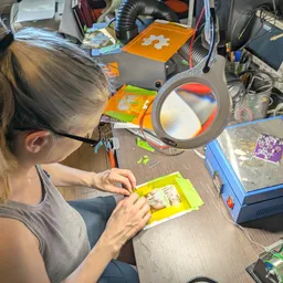
From there, I put all the parts on the board by hand, referring to KiCAD to ensure everything has the right value. Once all the parts are placed, the PCB goes onto the hotplate. At this point, proper and adequate ventilation is needed so you’ll see a tube that goes to a fume extractor next to my setup.

The hotplate is, well, hot. Hot enough that it melts the solder paste. This is the most gratifying moment of it all when the flux starts to burn off and the solder just sucks into the pads even if it’s a bit messy around it. It turns shiny and you can tell when things are soldered because the parts settle into the pads.
I pull it off the hotplate and let it cool. Some parts will need a bit of reinforcement so I’ll use wire solder to do that. Some parts tend to make solder bridges (again, this is probably minimized with better technique / more practice). Those get cleaned up. Then I hand solder the parts on the other side of the board.
From here one of us has to validate the hardware. Solder is a tricky beast and sometimes things LOOK connected but aren’t. Solder bridges happen. Values need to be changed or we need to bodge something together with a wire (the number of times we have handed Markus a prototype to test while saying, “be careful, it’s really fragile is definitely non-zero). So the first step is to make sure it works. Products that require firmware go to Stephen so he can write it since that needs to happen to validate the hardware.
Any hardware bugs get sent to me to update on the schematic and PCB for the next version, and if it's possible to modify the current revision with the needed changes, either Stephen or I will do it. And the validated hardware goes first to Markus so they can make us weep with the issues they find (and they will find issues).
Once all of that is incorporated, we start it all over again until we’re ready to build it for production.